Lexus GS300/400 (2000 year). Manual - part 139


  Index      Lexus     Lexus GS300/400 - service repair manual 2000 year


Search            


Content   ..  137  138  139  140   ..


Lexus GS300/400 (2000 year). Manual - part 139


EM0DD–03

A02689

SST

A02688

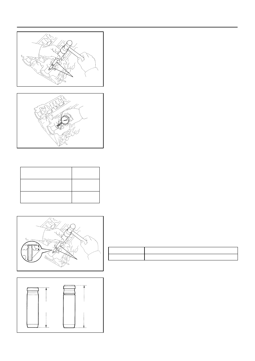
Bushing bore diameter
            mm (in.)

10.985 – 11.006 mm
(0.4325 – 0.4333 in.)

11.035 – 11.056 mm
(0.4344 – 0.4353 in.)

Both intake and exhaust

Bushing
    size

Use STD

Use O/S
   0.05

A02744

SST

P04791

Intake

Exhaust

38.5 mm
(1.516 in.)

40.5 mm
(1.594 in.)

EM–48

ENGINE MECHANICAL (2JZ–GE)

CYLINDER HEAD

1402

REPLACEMENT

REPLACE VALVE GUIDE BUSHINGS
(a)

Using SST and a hammer, tap out the guide bushing.
SST

09201–10000 (09201–01060),
09950–70010 (09951–07100)

(b)

Using a caliper gauge, measure the bushing bore diame-
ter of the cylinder head.

(c)

Select a new guide bushing (STD or O/S 0.05).

If the bushing bore diameter of the cylinder head is greater than
11.006 mm (0.4333 in.), machine the bushing bore to the follow-
ing dimension:

11.035 – 11.056 mm (0.4344 – 0.4353 in.)

If the bushing bore diameter of the cylinder head is greater than
11.056 mm (0.4353 in.), replace the cylinder head.

(d)

Using SST and a hammer, tap in a new guide bushing to
the specified protrusion height.
SST

09201–10000 (09201–01060),
09950–70010 (09951–07100)

Protrusion height:

Intake

12.3 – 12.7 mm (0.484 – 0.500 in.)

Exhaust

11.4 – 11.8 mm (0.449 – 0.465 in.)

HINT:
Different bushings are used for the intake and exhaust.

A02687

Sharp
6 mm
Reamer

ENGINE MECHANICAL (2JZ–GE)

CYLINDER HEAD

EM–49

1403

(e)

Using a sharp 6 mm reamer, ream the guide bushing to
obtain the standard specified clearance (See page

EM–40

) between the guide bushing and valve stem.

EM0D2–04

A11131

(d)

(g)

(f)

(e)

(b)

(c)

A11130

(h)

(i)

(j)

(k)

A11129

(o)

(n)

(o)

ENGINE MECHANICAL (2JZ–GE)

VALVE CLEARANCE

EM–5

1359

VALVE CLEARANCE

ADJUSTMENT

HINT:
Inspect and adjust the valve clearance when the engine is cold.
1.

REMOVE ENGINE COVER

Remove the 4 nuts and engine cover.
2.

DRAIN ENGINE COOLANT

3.

REMOVE INTAKE AIR RESONATOR

4.

REMOVE THROTTLE BODY AND INTAKE AIR
CONNECTOR ASSEMBLY

(a)

Disconnect the accelerator cable from the throttle body.

(b)

Disconnect the engine wire clamp from the clamp bracket
of the throttle body.

(c)

Disconnect the engine wire from the clamp on the throttle
body bracket.

(d)

Disconnect the accelerator pedal position sensor con-
nector.

(e)

Disconnect the throttle control motor connector.

(f)

Disconnect the throttle position sensor connector.

(g)

Disconnect the air assist hose from the intake air connec-
tor.

(h)

Disconnect the PCV hose from the intake air connector.

(i)

Disconnect the VSV connector for EVAP.

(j)

Disconnect the EVAP hose (from charcoal canister) from
the VSV for EVAP.

(k)

Disconnect the vacuum hose (from No.2 vacuum pipe)
from the No.1 vacuum pipe.

(l)

Remove the 2 nuts holding the throttle body bracket to the
cylinder head.

(m)

Remove the 4 bolts and 2 nuts holding the intake air con-
nector to the air intake chamber.

(n)

Disconnect the vacuum hose (from actuator for ACIS)
from the No.1 vacuum pipe.

(o)

Disconnect the 2 water bypass hoses from the throttle
body, and remove the throttle body together with the in-
take air connector and gasket.

A02638

A02651

A02664

EX

IN

1

3

5

2

4

1

3

5

2

4

1

1

EM–6

ENGINE MECHANICAL (2JZ–GE)

VALVE CLEARANCE

1360

5.

REMOVE NO.3 TIMING BELT COVER

Using a 5 mm hexagon wrench, remove the 4 bolts, oil filler cap,
timing belt cover and gasket.
6.

REMOVE IGNITION COILS AND HIGH–TENSION
CORD SET ASSEMBLY (See page 

IG–7

)

7.

REMOVE SPARK PLUGS

8.

DISCONNECT ENGINE WIRE FROM CYLINDER HEAD
COVERS

9.

REMOVE CYLINDER HEAD COVERS
(See page 

EM–33

)

10.

SET NO.1 CYLINDER TO TDC/COMPRESSION

(a)

Turn the crankshaft pulley and align its groove with the
timing mark ”0” of the No.1 timing belt cover.

NOTICE:
Always turn the crankshaft clockwise.

(b)

Check that the timing marks of the camshaft timing pul-
leys are aligned with the timing marks of the No.4 timing
belt cover.

If not, turn the crankshaft 1 revolution (360

°

).

11.

INSPECT VALVE CLEARANCE

(a)

Check only those valves indicated in the illustration.


Using a feeler gauge, measure the clearance be-
tween the valve lifter and camshaft.


Record the valve clearance measurements of those
that are out of specification. They will be used later
to determine the required replacement adjusting
shim.

Valve clearance (Cold):

Intake

0.15 – 0.25 mm(0.006 – 0.010 in.)

Exhaust

0.25 – 0.35 mm (0.010 – 0.014 in.)

(b)

Turn the crankshaft pulley 1 revolution (360

°

), and align

the groove with the timing mark ”0” of the No.1 timing belt
cover.


Content   ..  137  138  139  140   ..